Estimated reading time: mins

How to convert STL to STEP with free software?

How to Convert STL to STEP Using Free Software (Short Tutorial) 07:20
Using free software, we can convert a 3D scan (STL) into a CAD format (STEP). This process is called reverse engineering. We will reconstruct a solid model based on a 3D scan. This is not an automatic process, but a manual reconstruction. For this tutorial, we will use Netfabb (version 7.4.0) or Netfabb (current version) to measure the 3D scan. And the current version of FreeCAD (free CAD software) to redesign the part in CAD.
Table of Contents

Introduction

This tutorial covers the five basic steps to perform reverse engineering using FreeCAD and Netfabb.
This tutorial is intended for advanced FreeCAD users. We have also prepared a 120 min tutorial
video, which takes you, in detail, through each step.

  • With Netfabb (version 7.4.0) or Netfabb (current version) you can optimally measure the 3D scan (STL file). (It is also possible to measure directly in FreeCAD, but it works better in Netfabb).
  • With FreeCAD, you can design in CAD, and thus, create a solid model (STEP format).

The broken part, which serves as an example project, is a fuel sensor from a 50-year-old car. First, a
3D scan was made using the professional 3D scanner, Artec Space Spider. Then, a reverseengineered 3D scan was created using parametric modeling in FreeCAD.
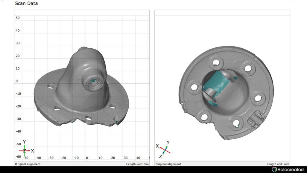
3D scan of a part inside the GOM inspect report
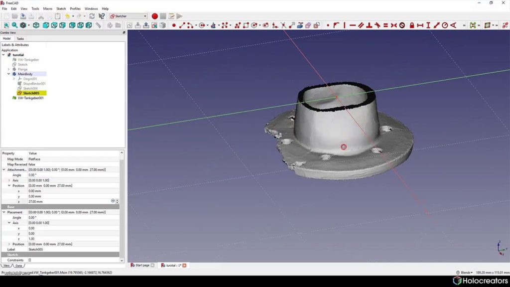
Swann Rack / Holocreators This is the original 3D Scan (STL format) of the tank sensor part. It was created with a professional 3D
scanner (Artec Space Spider). We have prepared the 3D Scan for download here.
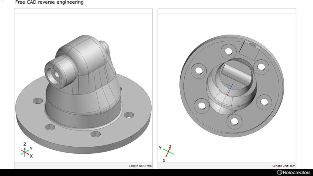
Swann Rack / Holocreators After reverse engineering using parametric modeling in FreeCAD, the finished solid model (STEP
format) looks like this. We have prepared the CAD file for download here.

Step 1: Measure the 3D Scan in Netfabb and create a reference sketch in FreeCAD

In this first step, a circle is defined using FreeCAD, which will help us align the 3D scan correctly.
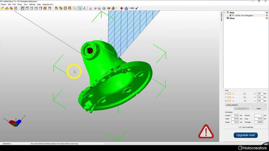
3D scan imported into Netfabb
Swann Rack / Holocreators The original 3D scan is imported,”professional-3d-scan-with-artec-space-spider-tankgeber-part.stl”,
into Netfabb. We have prepared the 3D Scan for download here.
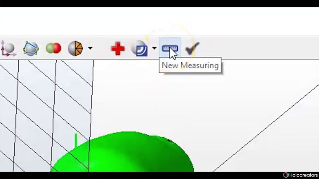
New measuring button in Netfabb
Swann Rack / Holocreators Click on the button “New Measuring”.
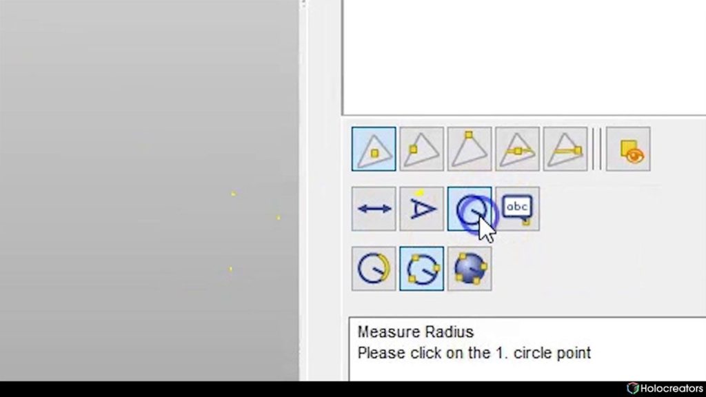
Measure radius button in Netfabb
Swann Rack / Holocreators Click on “Measure Radius”. The button “3 points on circle” must be activated.
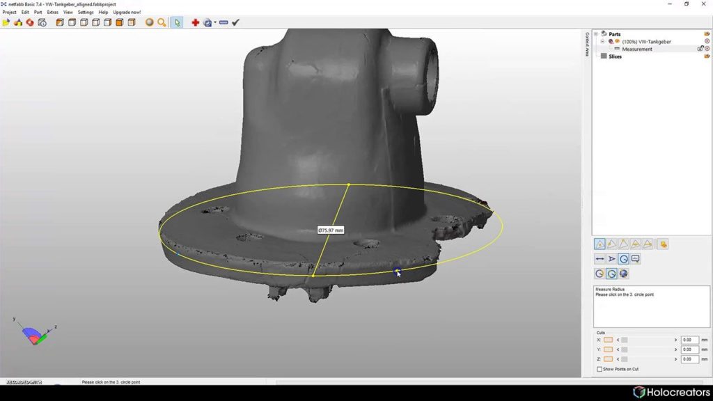
Three-points-on-circle function used to measure 3D scan diameter in Netfabb
Swann Rack / Holocreators Select the outer edge of the flange. Netfabb will automatically output the outer diameter.
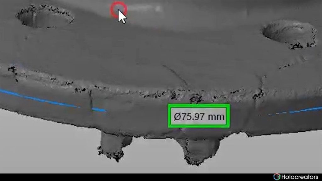
3D scan diameter measured in Netfabb
Swann Rack / Holocreators The outer diameter of the flange is 75.97mm—round up to 76mm.
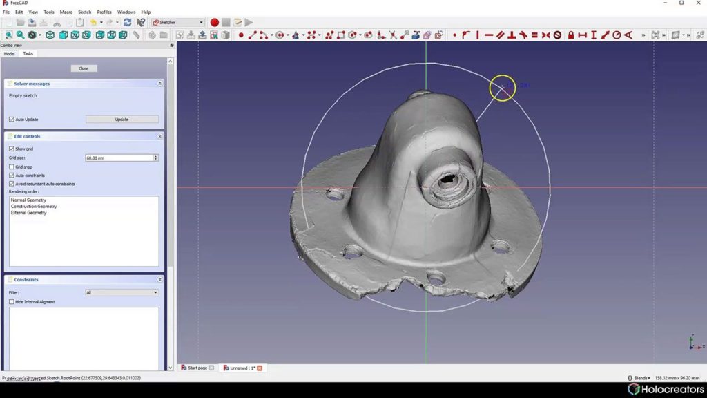
Creating a circle on the 3D scan with the sketcher in Freecad
Swann Rack / Holocreators Import the file “professional-3d-scan-with-artec-space-spider-tankgeber-part.stl” into FreeCAD and
activate the workbench “Sketcher”. Click on the button “Create a circle in the sketch”.
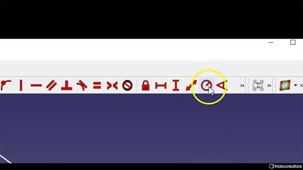
Fix the radius of a circle or an arc button in Freecad
Swann Rack / Holocreators Click on the button “Fix the radius of a circle or an arc”.
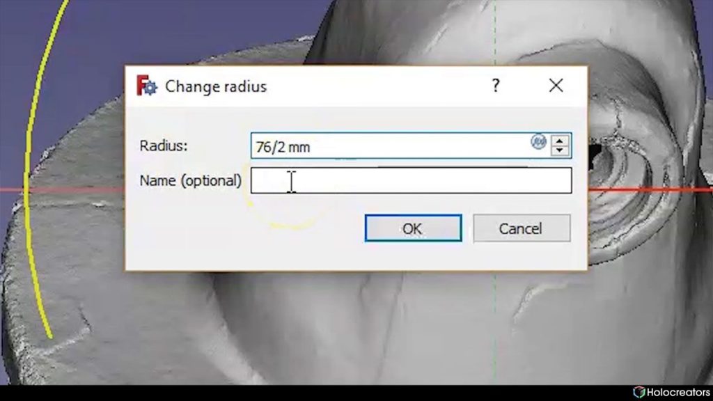
Window for radius change in Freecad
Swann Rack / Holocreators Enter the radius of the diameter. So 76mm/2 FreeCAD will automatically calculate the radius of
38mm. The reference circle sketch is now ready.

Step 2: Correct Alignment (Placement) of the 3D Scan in FreeCAD

Align the 3D Scan optimally along the X, Y and Z-axes. This is done in the “Sketcher” workbench.
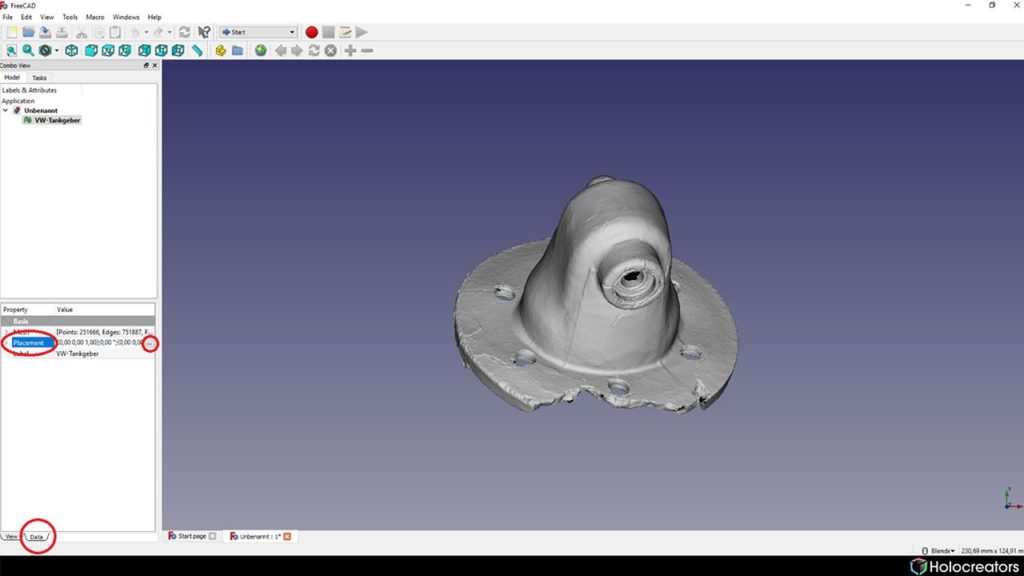
Data tab in Freecad
Swann Rack / Holocreators In the lower-left hand corner, click on the button “Data”.
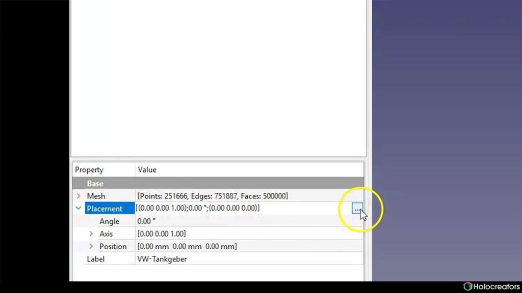
Placement tab and three dots button in Freecad
Swann Rack / Holocreators Click on the three dots next to the “Placement” button.
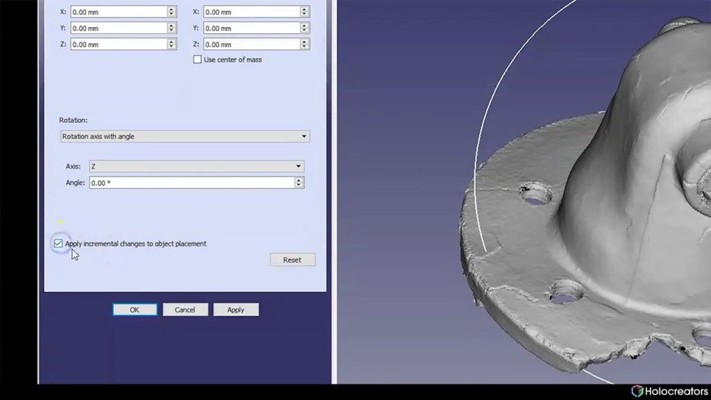
Checkbox to apply incremental changes to object placement in Freecad
Swann Rack / Holocreators Activate the checkbox “Apply incremental changes to object placement”.
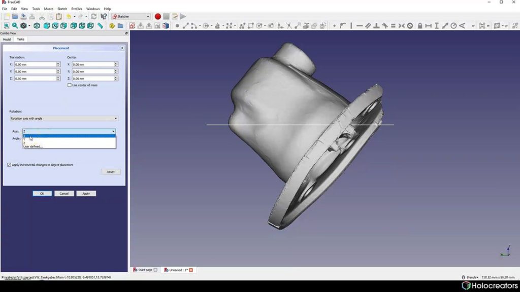
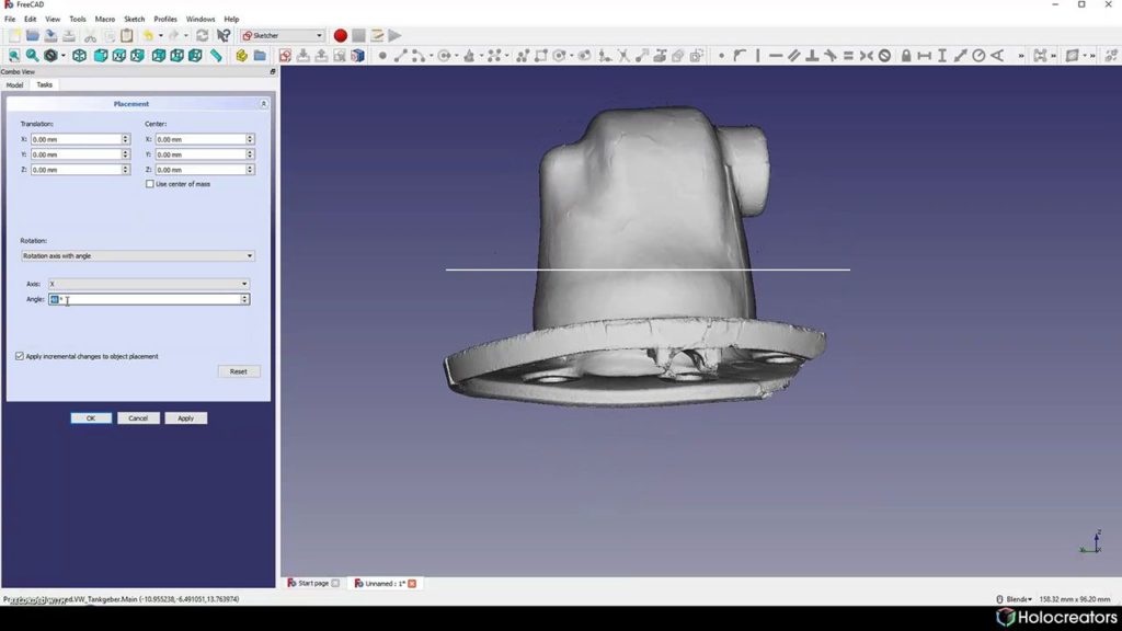
Rotating the 3D scan along its x-axis in Freecad
Swann Rack / Holocreators Switch to a side view and rotate the 3D Scan incrementally until it is aligned perpendicular to the Xaxis.
Rotating the 3D scan in Freecad so its perpendicular to the reference circle
Swann Rack / Holocreators In the end, it should look like this.
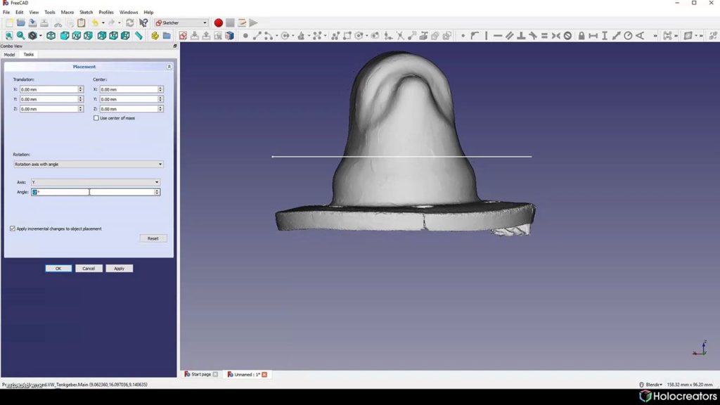
Rotating the 3d scan along its y-axis in Freecad
Swann Rack / Holocreators Change the view and repeat the process for the Y-axis.
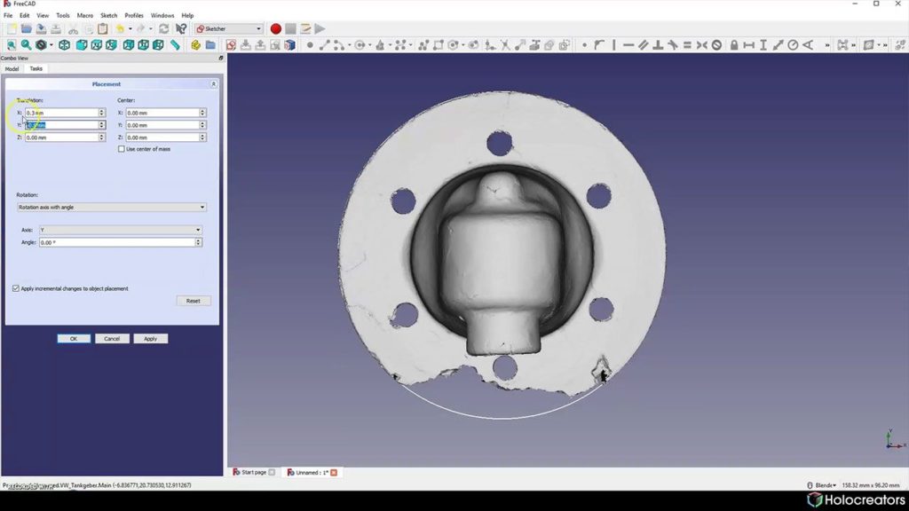
Moving the 3D scan until its in the center of the reference circle
Swann Rack / Holocreators Finally, switch to a top view and move the 3D Scan until it is in the center of the circle. The 3D Scan is
now optimally aligned in the FreeCAD coordinate system. This will simplify the CAD modeling process.

Step 3: Change the Transparency of the 3D Scan in FreeCAD and Create a Profile

Adjust the 3D scan to make it semi-transparent to allow for designing directly on it.
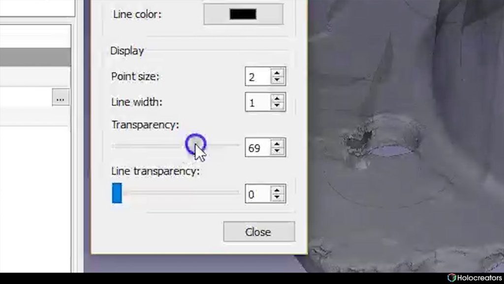
Transparency slider in Freecad
Swann Rack / Holocreators The key combination CTRL+D opens a window in which we can set the “Transparency”.
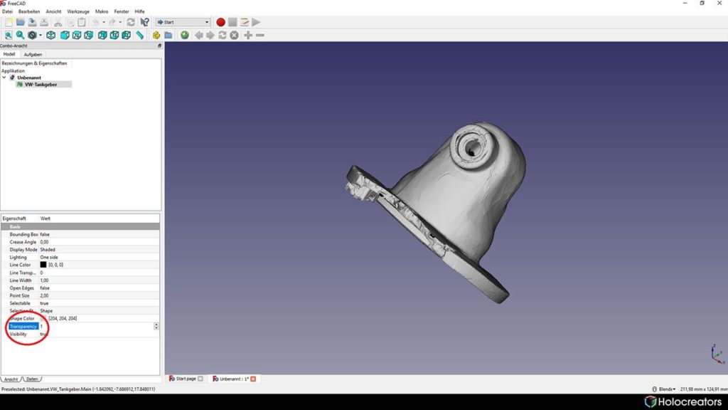
Transparency tab in Freecad
Swann Rack / Holocreators If CTRL+D does not work, you can set the “Transparency” directly in the menu’s lower-left hand
corner.
Create new Sketch button in Freecad close-up
Swann Rack / Holocreators Click on “create new sketch” to enter the ”sketcher” workbench.
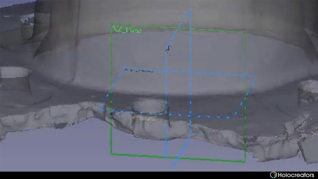
Selection of X-Z plane in Freecad
Swann Rack / Holocreators Select the XY layer.
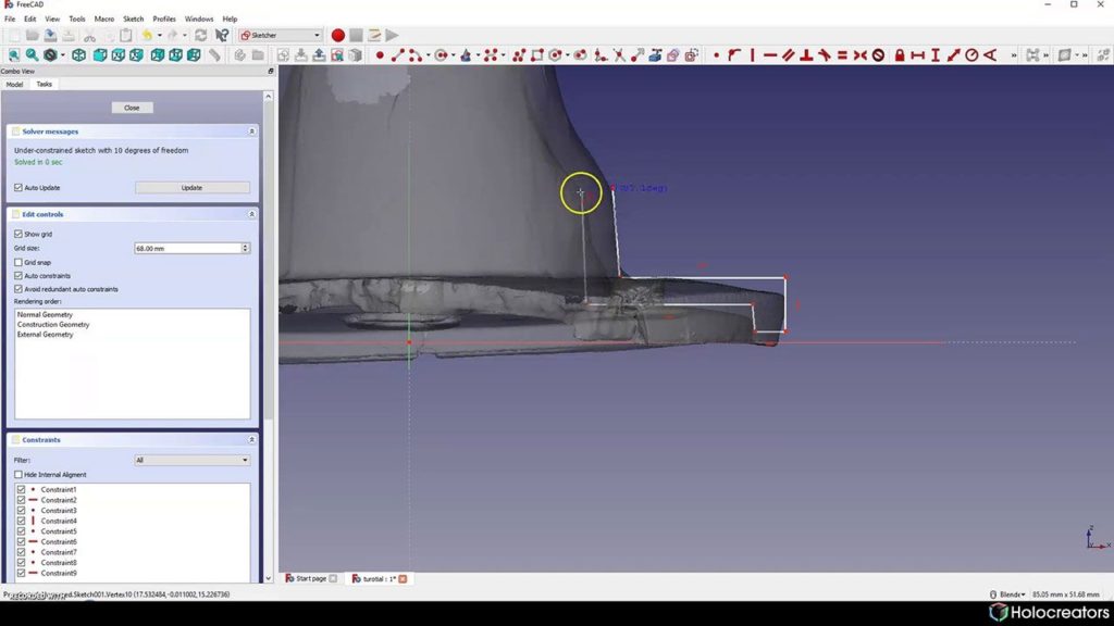
Sketching on the cross-section of a 3D scan in Freecad
Swann Rack / Holocreators Design on the cross-section of the flange.
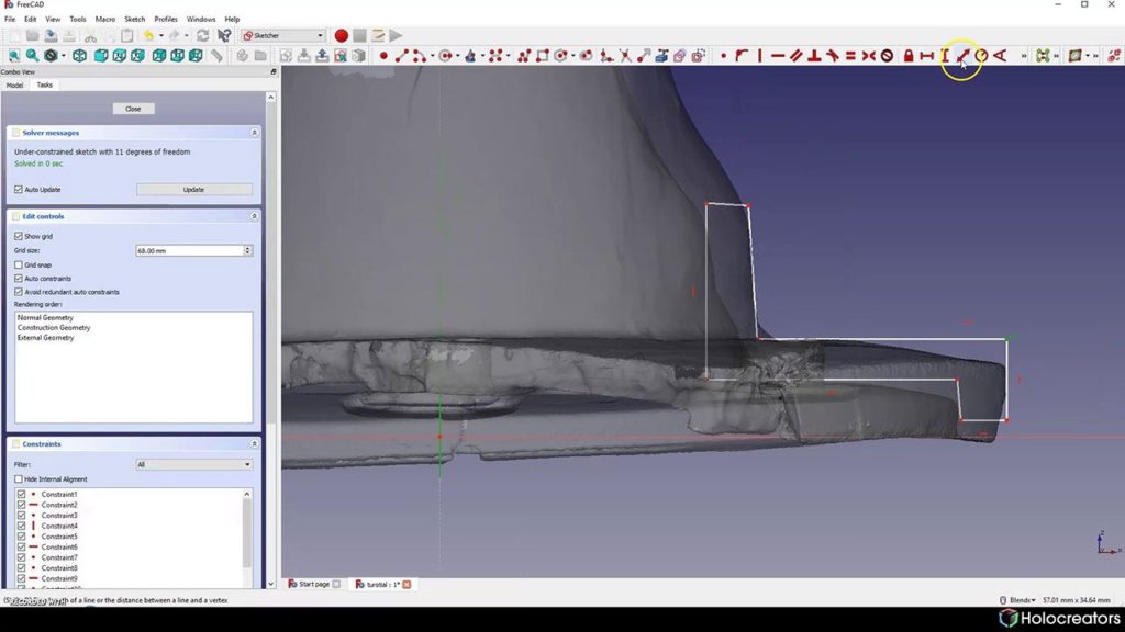
Fix the length of a line or the distance between a line and a vertex button in Freecad
Swann Rack / Holocreators Click on “fix a length of a line or the distance between a line and a vertex “.
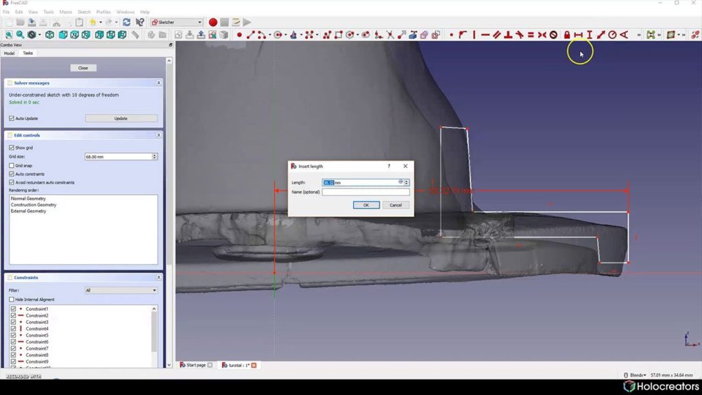
Window to insert length in Freecad
Swann Rack / Holocreators Define the dimension between the edge of the flange and the center. The radius is 76mm/2=38mm. A
frequent change between Netfabb and FreeCAD is necessary until all constraints are defined for the
sketch.
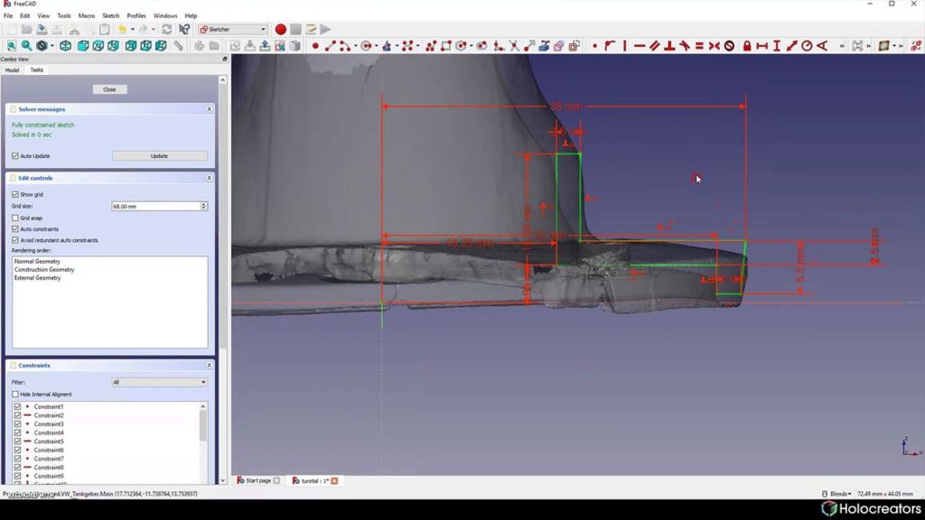
Fully-constrained green sketch in Freecad
Swann Rack / Holocreators When all constraints have been defined, the sketch will turn to green.
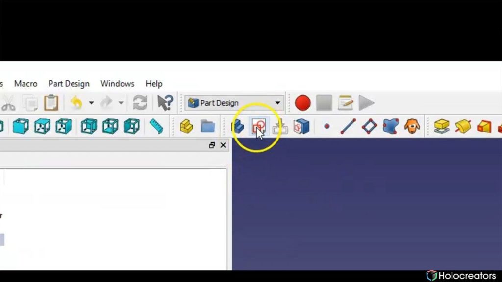
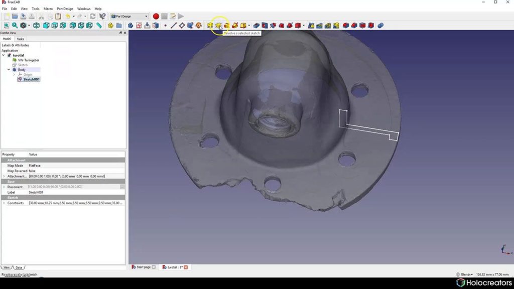
Revolve a Selected Sketch button in Freecad
Swann Rack / Holocreators In the workbench ”Part Design” click on “Revolve a selected sketch”.
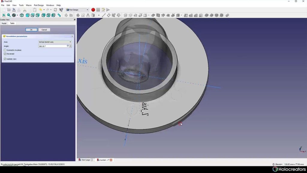
CAD model of the basic flange shape in Freecad
Swann Rack / Holocreators After revolving, the basic geometry of the flange is complete. Further sketches optimize the shape.

Step 4: Hide Areas of the 3D Scan and Sketch on the Cross-section.

The following steps can be performed in the “Mesh Design” workbench.
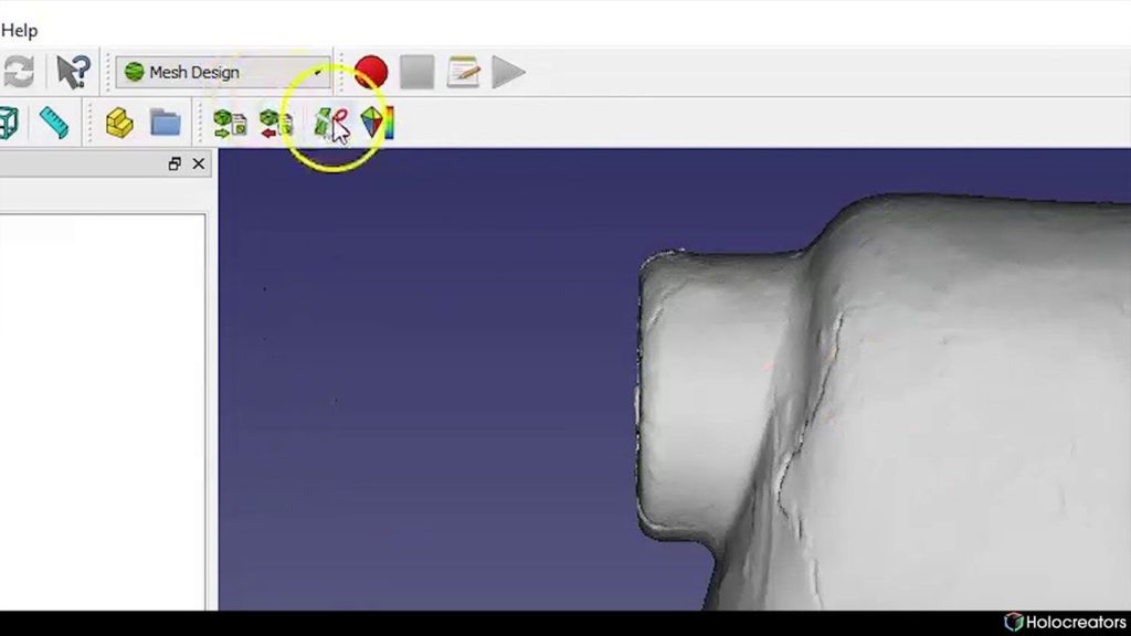
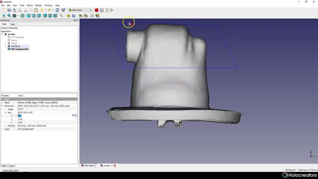
Cuts a mesh with a picked polygon button in Freecad
Swann Rack / Holocreators Click on the button “Cut a mesh with a picked polygon”.
Blue selection line in Freecad
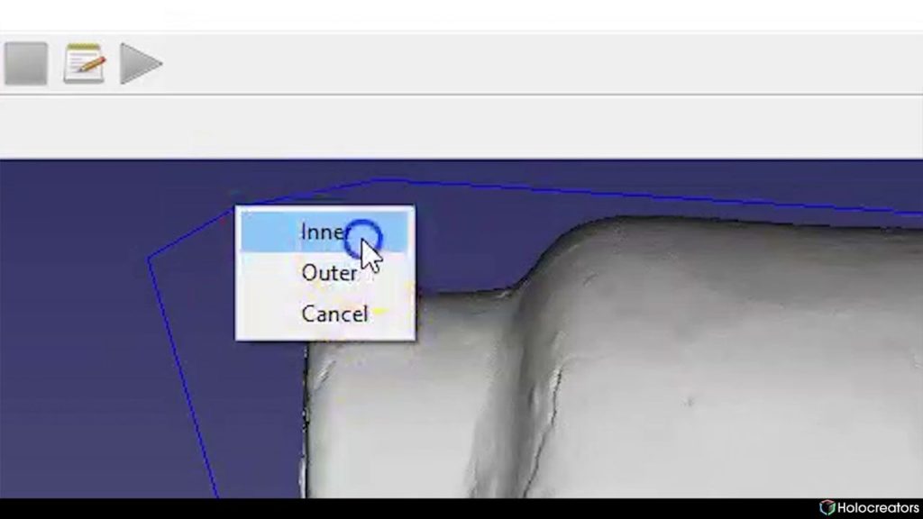
Swann Rack / Holocreators With the outlined blue area, we define the section of the 3D Scan to hide.
Select inner after using the blue selection line in Freecad
Swann Rack / Holocreators After we have completed the selection, right-click and select “Inner”.
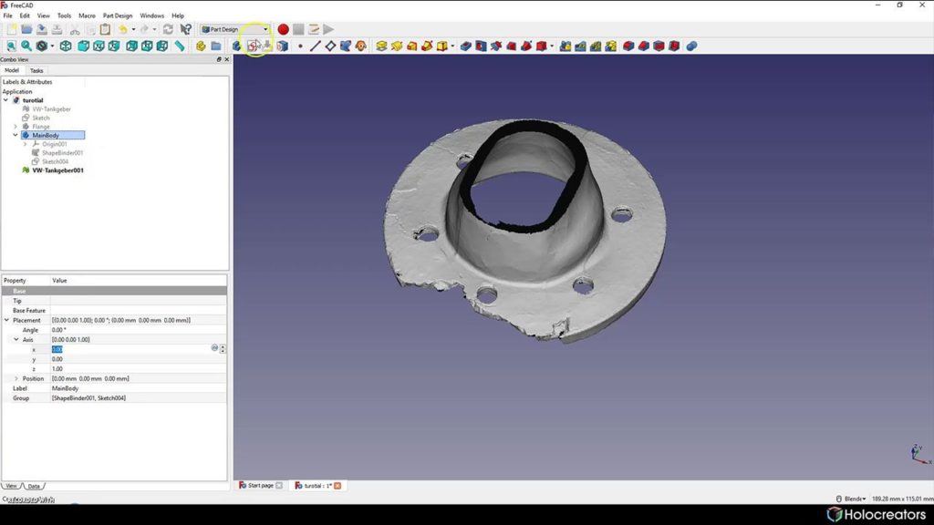
Create new Sketch button in Freecad
Swann Rack / Holocreators Switch to the “Sketcher” workspace and click on “Create new sketch”.
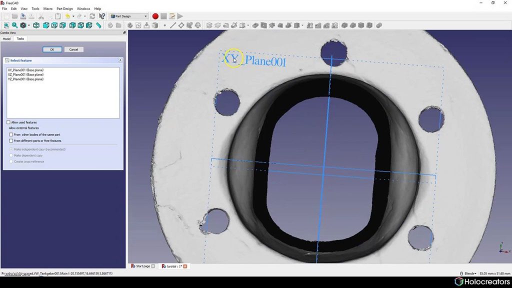
Selection of X-Y plane in Freecad
Swann Rack / Holocreators Select the XY plane.
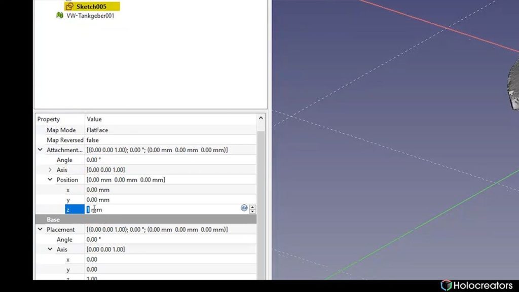
Changing the z-position of the plane in Freecad
Swann Rack / Holocreators In the “Position” menu, change the Z-axis until the plane is at the same height as the cut edge.
Adjusting the plane in Freecad so its on the cross-section of the 3D scan
Swann Rack / Holocreators The result should look like this.
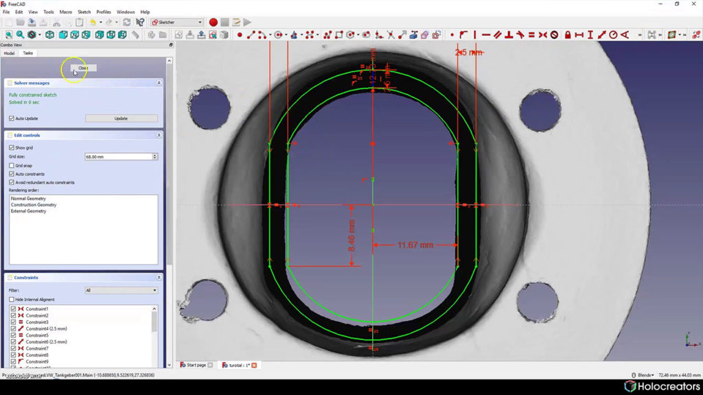
Fully constrained sketch on the cross-section of a 3D scan in Freecad
Swann Rack / Holocreators We switch to the top-view and sketch on the cross-section of the 3D Scan.

Step 5: Connect Profiles with a Loft.

Depending on the complexity of the part, many different profile sketches must be created to
determine the outer shape. Continue working in the “part design” workbench. The profiles are
connected with a loft to form a closed solid.
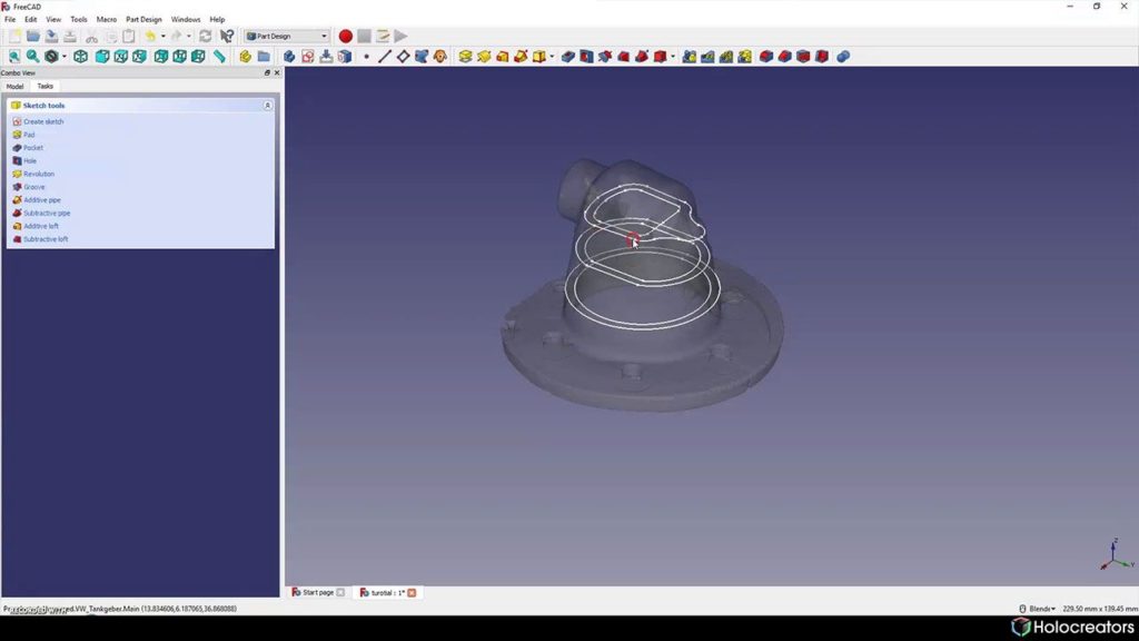
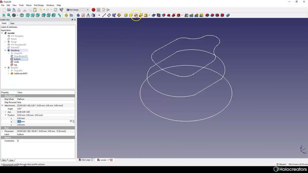
Profiles for lofting in Freecad
Swann Rack / Holocreators These three profiles are to be connected to form a loft.
Loft profiles in Freecad
Swann Rack / Holocreators For the sake of simplicity, first concentrate on the outer shape.
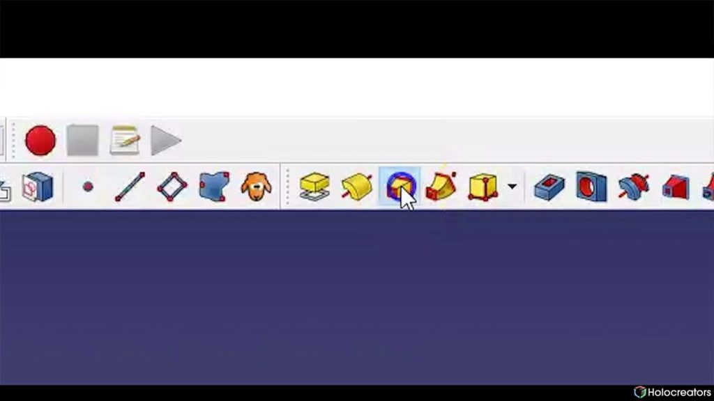
Loft a selected profile through other Profile Sections button in Freecad
Swann Rack / Holocreators Click on ” loft a selected profile through other profile sections.”
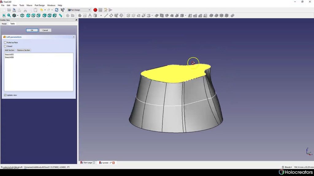
Result of lofting operation in Freecad is a solid model
Swann Rack / Holocreators The result of the lofted profiles should look like this.

Step 6: Connect the Individual Bodies with the Boolean Operation and Export Them as a STEP File.

In this last step, connect the single bodies and export them as a STEP file. For this phase, continue
working in the workbench “Part”. Not all bodies need to be created with lofting. Some can be
created with very simple geometry.
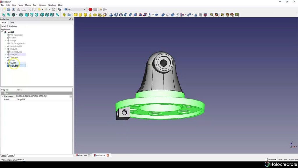
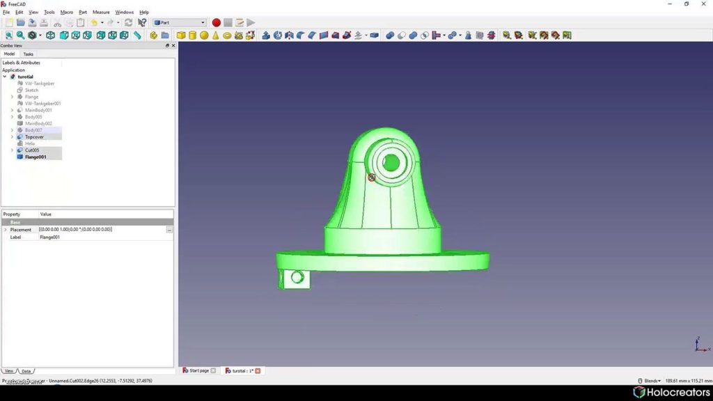
Selection of seperate bodies in Freecad
Swann Rack / Holocreators First, select the flange body.
Selection of all bodies in Freecad
Swann Rack / Holocreators Then select all other bodies.
Boolean operation with two or more bodies in Freecad
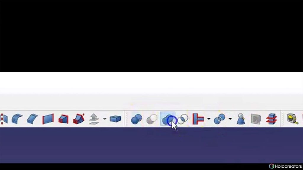
Swann Rack / Holocreators Click on “Boolean operation with two or more bodies” to connect all bodies.
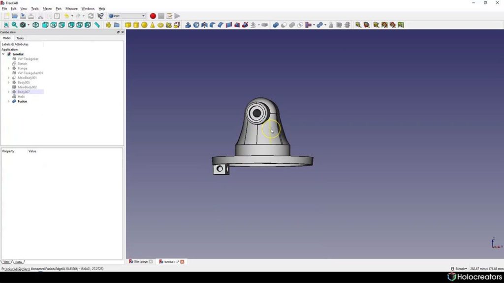
Reverse engineered solid model from 3D scan in Freecad
Swann Rack / Holocreators The result is the finished CAD solid model.
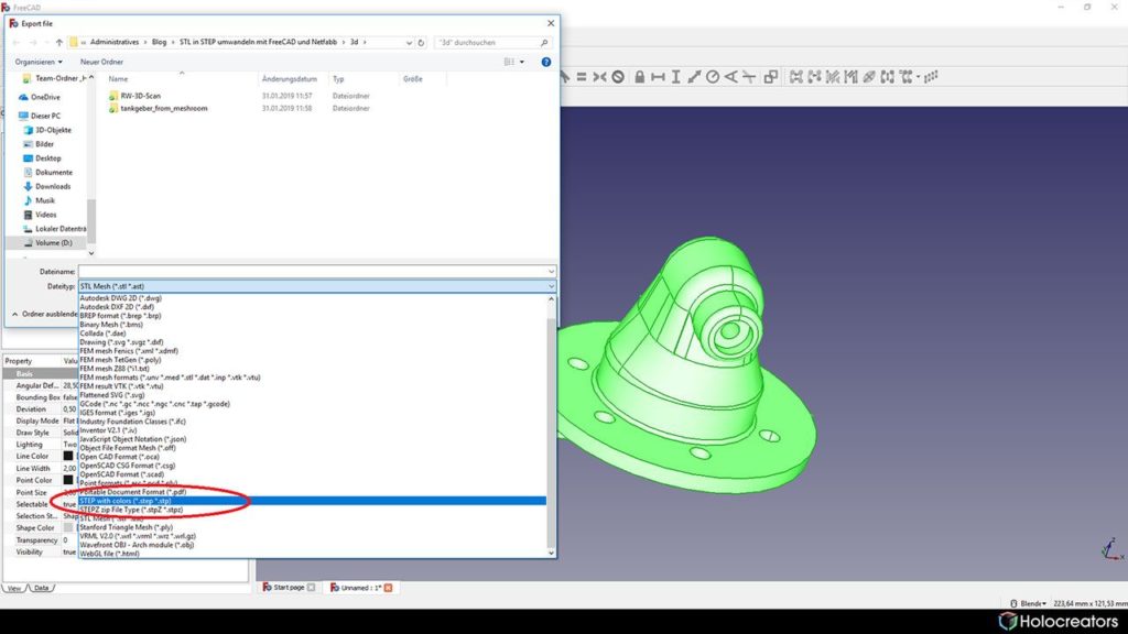
Saving the selected part in step format in Freecad
Swann Rack / Holocreators The solid model can now be exported as a STEP file. You can download the finished STEP file here.

Step 7: Compare the Newly Constructed Solid Model (STEP) with the Original 3D Scan (STL)

Create a report to compare the newly generated solid model in FreeCAD with the original 3D scan.
This is a deviation analysis. To create this analysis, we used the free software GOM Inspect.
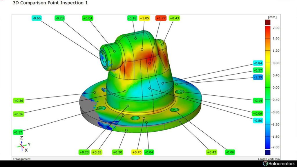
Side-view of the deviation analysis between the original 3D scan and the reverse-engineered solid model
Swann Rack / Holocreators This picture shows the deviation between the 3D Scan (STL) and the solid model (STEP) in mm. You
can download the deviation analysis here.
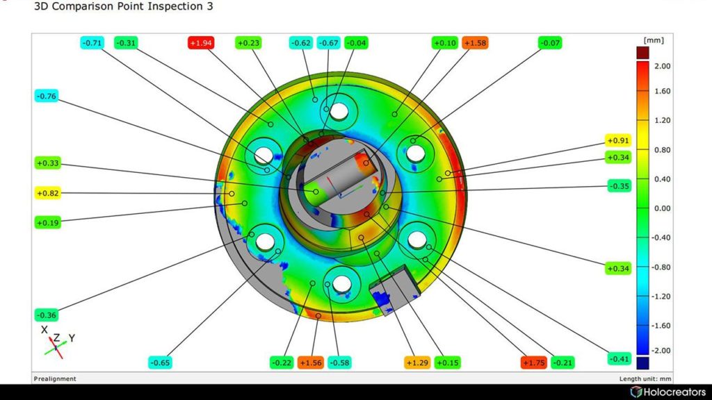
Bottom-view of the deviation analysis between the original 3D scan and the reverse-engineered solid model
Swann Rack / Holocreators The different colors show the degree of deviation.

Explanation of the Colors

  • Green means there is hardly any deviation between the original 3D Scan and the newly
  • created solid model.
  • Red means that the new solid model overlaps the original 3D Scan at this point.
  • Blue means the new solid model is under the original 3D Scan.

Project Files Available for Download

We have prepared all project data for download, including the original 3D scan, the CAD solid model
and the deviation analysis.

Summary

The reverse engineering was very successful. There are differences between the 3D scan and the
CAD model, which we have created, but the original part was heavily deformed, and our
reconstruction is therefore much better than the original.

Do you need help converting an STL to a STEP file?

Holocreators offers professional 3D-scanning and reverse engineering services. We would love to
help you with converting your files from STL to STEP. Please call us at +49 40 481133 or send an email info@holocreators.com
Swann has been enthusiastic about everything 3D for many years. His roots lie in analog holography, which brought him to digital 3D-modeling in 2011.

The rapid progress of various 3D-scanning techniques fascinated himso much thathe founded Holocreators together with his brother Miro Rack in 2015.

Ready to get started?
  • JPG, PDF, or PNG max 100 MB
    Drop files here or
    Accepted file types: jpg, png, pdf, jpeg, Max. file size: 100 MB.
    You may be interested
    Estimated reading time: mins
    With the help of specialized 3D scanners, you can 3D-scan people and animals. This allows you to create 3D models that can be 3D-printed or used for 3D animation. We'll show you three different devices that make such 3D scans possible.
    Estimated reading time: mins
    Kitbashing is associated with model making. It is composed of the words "Kit" and "Bashing". “Kit” refers to "model kit". So, when a model maker is "kitbashing", he blends parts from different model kits. Similar to a collage. The model maker combines several individual models into an entirely new model.
    Estimated reading time: mins
    A NURBS model consists of points connected by curves. A polygon mesh consists of thousands or millions of small triangles. CAD surface models are usually created using NURBS surfaces, while 3D scans are typically exported as a polygon mesh. The conversion from a polygon mesh to a NURBS model is called "reverse engineering".
    Estimated reading time: mins
    Reverse engineering enables us to create a copy of an object. For this purpose, the part is 3Dscanned, then the 3D scan data is converted into a CAD format, and finally, the part is manufactured. All these steps result in noticeable deviations. If an error adds up over multiple steps, then we call this error propagation.

    Thanks you!

    Our representative will be in touch with you soon

    Thanks you!

    We are glad that you have subscribed to our newsletter
    sparks