We convert 3D scans into CAD models. From STL to STEP.



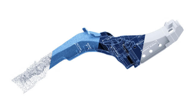

We offer the service of converting a 3D scan (STL) into a CAD format (STEP). This process is called reverse engineering. We distinguish between two variants for the conversion. Either we use surface modeling or parametric modeling to convert the 3D scan into a CAD model. The parts geometry and the final application determine the method to be used. For each method, we have created a video and written a detailed article.

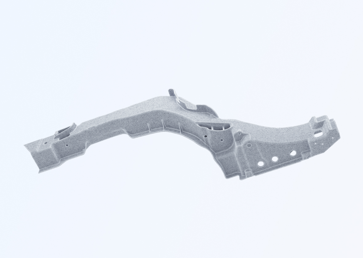
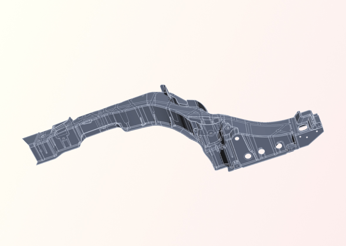
The goal is to preserve the current state of the 3D-Scan. The scan is transformed into a highly precise CAD model using NURBS surface modeling.
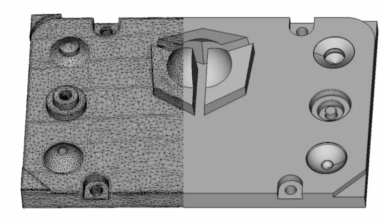
The goal is to create an optimized parametric reconstruction of the 3D scan as a CAD model.

This technique allows us to convert a 3D scan into the native CAD format or whatever CAD software our client is using.
We 3D scan your part or work based on the 3D scan data you provide.
We convert the 3D scan into a CAD model, either as a parametric model or as a surface model, which we always close into a solid.
The generated CAD data will be made available for download on our server.
Reverse engineering refers to the conversion of a
3D scan into a CAD format, for example from STL to STEP.
You may watch the video to get a better idea of the process.
In the first step, we create a 3D scan (STL) of your part. Alternatively, you can provide your own 3D scan. Then, we convert the 3D scan (STL) into a CAD format (STEP).
We can also convert the 3D scan into the native format of your in-house CAD software. Then the CAD model will have a feature history where all parameters can be accessed and adjusted.


Depending on the selected reverse engineering method,
we provide the data either in neutral CAD exchange formats such as STEP, IGES, or X_T, or in the native CAD format of your in-house CAD software.
We offer the service of converting a 3D scan (STL) into a CAD model (STEP) using surface modeling. This process involves molding the 3D scan with NURBS surfaces, transferring the current state of the object into a CAD model. The resulting CAD model consists of freeform surfaces, making it ideal for measurements in CAD or as a reference model. It is not suitable for further modeling as the NURBs surfaces are almost impossible to edit.
Reverse engineering to solid model allows the conversion of a 3D scan (STL) into a CAD solid model (STEP). The goal is to keep the deviations between the 3D scan and solid model as small as possible. There is no correction of manufacturing defects of the 3D scanned part so that accuracy can be maintained. The resulting solid model can consist of simple geometries or complex NURBs surfaces. When simple geometry and NURBS are combined in one model, it’s sometimes called a “hybrid”.
We offer the service of converting a 3D scan (STL) into a CAD model (STEP) using parametric modeling. This is a precise reverse engineering process. The 3D scan is optimized during the conversion to CAD and rebuilt with parametric geometry. Areas not captured in the 3D scan are logically added. Inaccuracies are corrected and adjusted according to standards. Upon request, we also provide the CAD data with feature history and technical drawings. Additionally, we can export the data in the clients in-house CAD software format.
We make videos about 3D-scanning and reverse engineering. We will happily inform you when a new video goes online.
We offer a professional 3D scanning service as well as
3D scan to CAD conversion services.
Feel free to contact us for advice on your individual project.


