3D Scan to CAD Conversion Service with Parametric Modeling (Parametric Reconstruction)
We offer the service of converting a 3D scan (STL) into a CAD model (STEP) using parametric modeling. This is a precise Parametric Reconstruction. The 3D scan is optimized during the conversion to CAD. Areas not captured in the 3D scan are logically supplemented. Inaccuracies are corrected and adjusted according to standards. Upon request, we also provide the CAD data with feature history and technical drawings.




How We Do It?
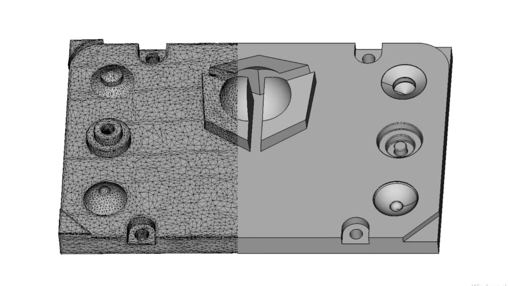
How do we do it?
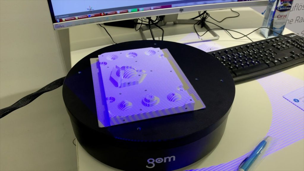
In the beginning, we create a 3D scan (STL) to capture the geometry of the part. Alternatively, the customer can also provide their own 3D scan. The 3D scan serves as the basis for completely reverse engineering the object into a CAD model. The 3D scan is used only as a reference. The resulting CAD model thus has an idealized and optimized shape. (For example, a scanned angle of 89.5° will be corrected to 90° by us, as this was most likely the intention during the original design.) During the reverse engineering process, we can also compensate for areas that were not captured in the 3D scan. Depending on the level of optimization, the reverse engineering has a deviation of 0.05 mm to 0.25 mm compared to the original 3D scan.
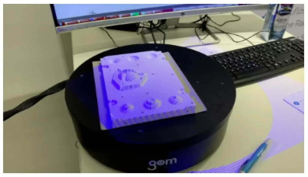
Our goal
The goal is to provide the customer with a parametric CAD model, based on which they can continue their design. We provide the data either as a STEP model or, upon request, in the native CAD format, meaning the format of the CAD software the customer is using. (For example, if the customer works in FreeCAD, we can deliver the data in FreeCAD’s native CAD format .FCStd.) In the native CAD format, the entire feature history is included, and the customer can individually access and modify any parameters.
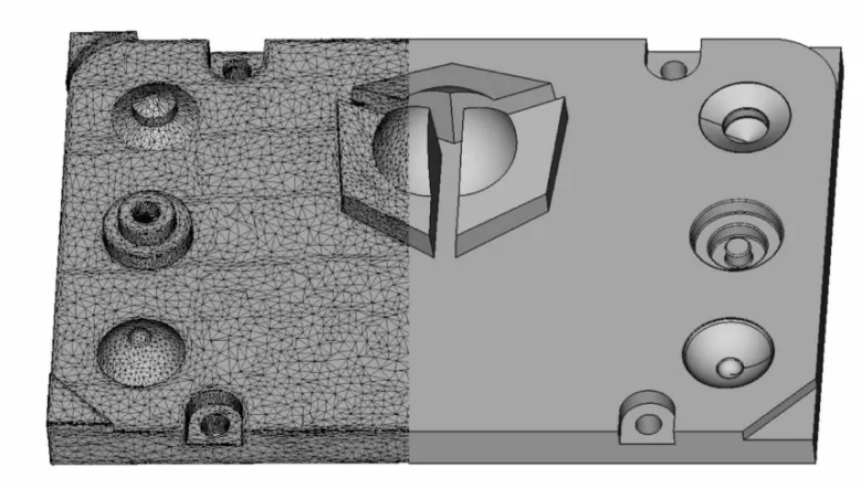
Upon Request, with Feature History and Technical Drawing
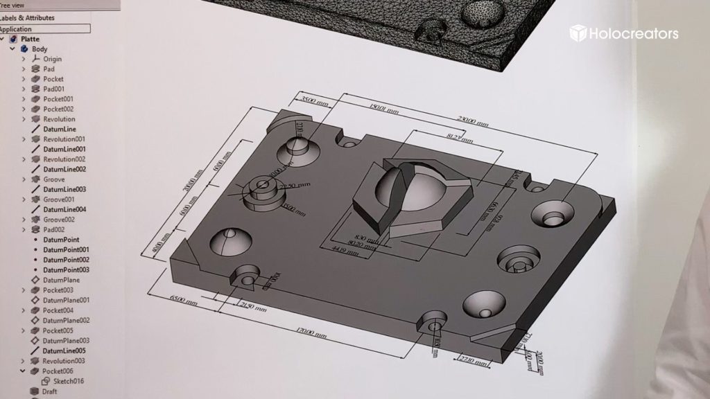
Since the CAD model is parametrically modeled, we can also export a CAD file with feature history upon request. If this is desired, we should coordinate with the customer in advance regarding their CAD software and version number to ensure that our data can be easily processed later. We offer this service for all common CAD software currently available on the market. A CAD model with feature history is also a prerequisite for creating a technical drawing.
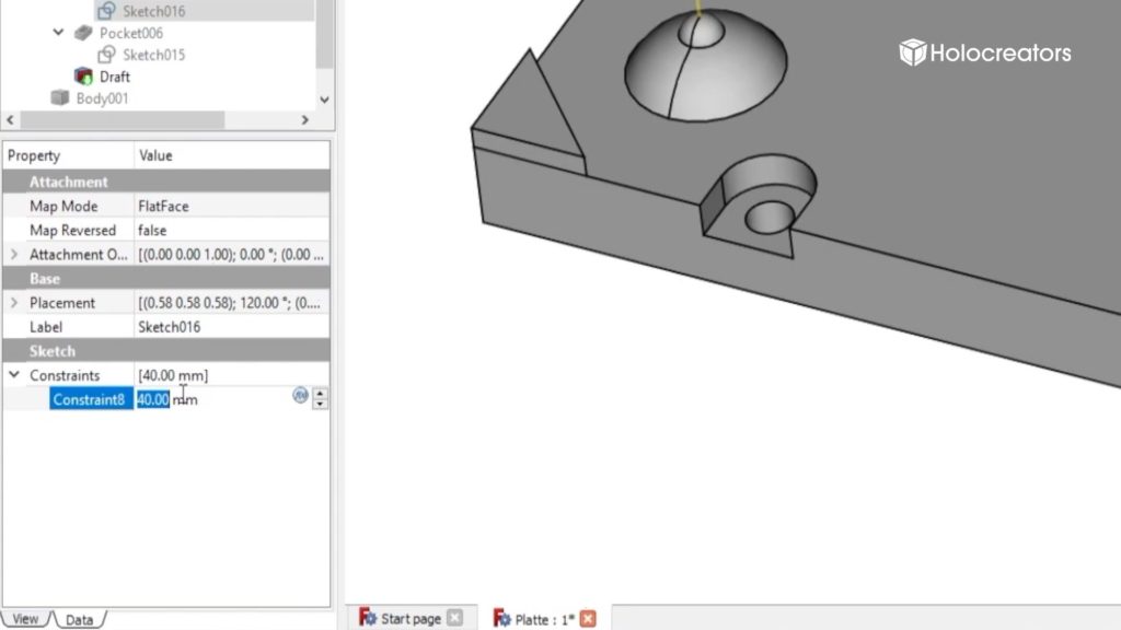
The goal
Keep in mind that the “reverse engineering to parametric model with a history tree” is an optimized form of the 3D scan. For example, a scanned angle of 89° is corrected by us to an angle of 90°. Inaccuracies are corrected according to engineering standards.
This reverse engineering technique is the prerequisite for a technical drawing.
Real world example
Holocreators offers this reverse engineering service to paramatric model with a history tree for every CAD Software on the market.
Advantages and Disadvantages of Converting a 3D Scan to CAD with Parametric Modeling
Advantages:
- Ideal for Further ModelingThe CAD model created with parametric modeling can be edited and modified.
- Small File Size The parametric CAD model is very efficiently structured has therefore a small file size.
- Upon Request, with Feature HistoryExport in the native format of the client's in-house CAD software. Then the CAD model will have a feature history where all parameters can be accessed and adjusted.
- Upon Request, with Technical Drawing The feature history also allows the creation of a technical drawing.
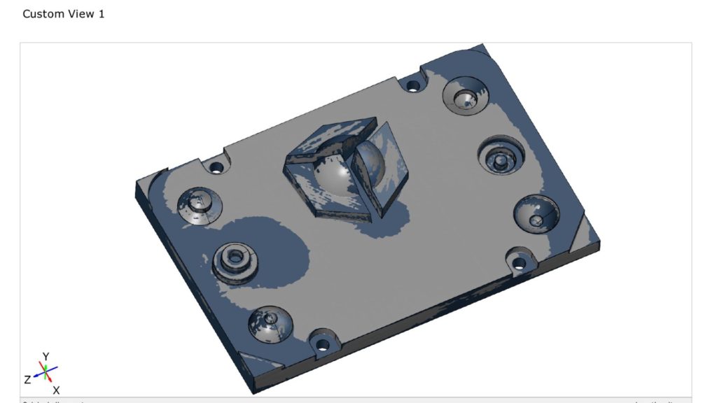
- Deviation Analysis between Original 3D Scan and CAD Model. Comparison of the created CAD model to the original 3D scan using a color-coded deviation analysis.
Disadvantages:
- Less Accuracy Compared to surface modeling, where we mold the 3D scan with high precision, parametric modeling is less accurate. The average deviation between the 3D scan and the parametric CAD model is between 0.05 mm and 0.25 mm.
- Organic shapes are difficult to model parametrically Only with considerable effort is it possible to parametrically model organic-shaped parts; surface modeling is better suited for this.
Example Data to Download
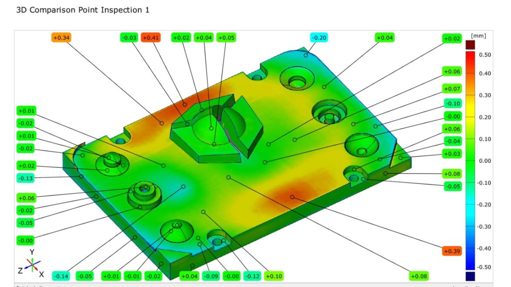
As an example, we have converted a 3D scan with parametric modeling into a CAD model and prepared it for download. The CAD model with feature history, as well as a deviation analysis, are also included. For viewing, the free CAD software FreeCAD is recommended.
Get to know more
Frequently Asked Questions
By reverse engineering with parametric modeling we create a CAD model based on a 3D scan (STL). The 3D scan is only used as a reference, while the CAD model is completely re-modeled parametrically. The reverse engineering is usually output in STEP format, but can also be exported in the native format of the client’s proprietary CAD software.
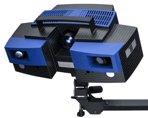
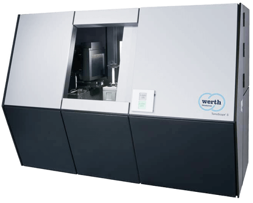
The basis for a reverse engineering using parametric modeling is a 3D scan. The customer can provide this 3D scan themselves, or we can perform the 3D scanning of the part in-house. Depending on the parts shape, we create the 3D scan using either 3D CT scanning or an optical 3D scanner.
During the conversion, a CAD model is created based on the 3D scan (STL). The 3D scan is loaded into a reverse engineering software, and the CAD model is then manually re-constructed parametrically. The resulting CAD model can then be exported either as a STEP file or in the native format of the customer’s in-house CAD software.
The 3D scan to CAD conversion using parametric modeling typically has a deviation of 0 to 0.25 mm compared to the original 3D scan.
Upon request, we can provide the CAD model from our parametric reverse engineering with a feature history. To ensure compatibility, we should discuss the customer’s CAD software and version number before starting the project.
The parametric CAD model can be provided in STEP, IGES, or XT formats. Upon request, we can also provide it in the format of the customer’s in-house CAD software.
Subscribe to the Holocreators Newsletter
We make videos about 3D-scanning and reverse engineering. We will happily inform you when a new video goes online.
Do you need Support with Your Project?
We offer a professional 3D scanning service as well as a 3D scan to CAD conversion service.
Feel free to contact us for a personalized consultation for your individual project.”

