We offer the service of converting a 3D scan (STL) into a CAD model (STEP) using surface modeling. This process involves molding the 3D scan with NURBS surfaces, transferring the current state of the object into a CAD model. The resulting CAD model consists of freeform surfaces, making it ideal for measurements in CAD or as a reference model. It is not suitable for further modeling as the NURBs surfaces are almost impossible to edit.
The process starts with the 3D scan, which we use to capture the geometry of the part. This 3D scan forms the basis for creating a CAD model. Alternatively, the customer can also provide their own 3D scan.
In the reverse engineering software, we use automatic (Autosurface) or semi-automatic (Boundary Fit) functions to digitally replicate the 3D scan as accurately as possible. It is very similar to creating a mold.
The resulting CAD model is a surface model, consisting of numerous individual NURBS surfaces. However, the customer usually requires a closed solid model, so our main effort lies in manually closing the surface model. This can be particularly time-consuming when there surfaces missing in many areas.
The final CAD model typically has an average deviation of 0.05 mm from the original 3D scan.
The goal is to provide the customer with a CAD model that deviates only minimally from the original 3D scan. The focus is on capturing the current state of the 3D Scan.
Since the 3D scan is directly replicated, any irregularities in the scanned component are also carried over. As a result, the customer receives the exact current state of the component in their CAD system and can make precise measurements or use the data as a reference model.
The finished CAD model consists of many small NURBS surfaces, which means that later adjustments to the geometry by the customer are not possible. We always deliver the CAD data as a closed volume model.
With surface modeling, customers often fear that the delivered CAD model will not be in the form of a closed solid model. This concern is unfounded.
We place special emphasis on ensuring that all of our delivered CAD models are watertight and fully closed to the volume model.
It depends on the parts geometry and the intended use which type is used.
To help you better understand the differences between
Auto Surface and Boundary Fit, we have prepared the
various CAD models for download:
As a starting point for the conversion, we need a 3D Scan (STL).
Next, reverse engineering software is needed to reconstruct a CAD model (STEP) based on the 3D scan.
Using surface modeling, the existing 3D scan (STL) is converted into a CAD format (STEP).
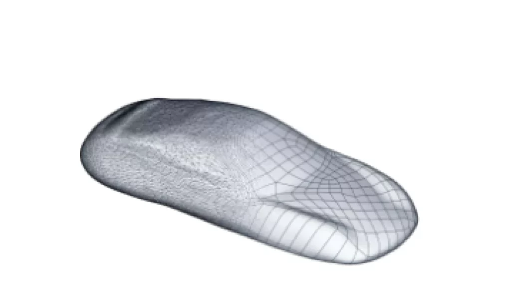
The underlying 3D scan is then molded from NURBS surfaces (freeform surfaces).
There are two different options: Either this is done fully automatically (“Auto Surface”), or the guide curves are manually defined, and the surfaces in between are automatically generated (“Boundary Fit”).
The choice of method depends on the parts geometry and the intended application. Both methods result in a surface model that can be closed into a volume model. However, the geometry of the resulting CAD model can hardly be modified by the customer later on.
After successful conversion, the 3D data is output as a CAD model.
It is a surface model that has been closed into a solid model.
The CAD model can be exported in the following formats: STEP, IGES, or X_T.
On average, the generated surface model deviates by up to 0.05 mm from the original 3D scan (STL).
This high accuracy is achieved through the automatic molding of the surfaces from the underlying 3D scan.
With every conversion, we create a deviation analysis that compares the original 3D scan (STL) with the generated CAD model (STEP). Any deviations are visualized using a color scheme.
We offer a professional 3D scanning service as well as a 3D scan to CAD conversion service.
We make videos about 3D-scanning and reverse engineering. We will happily inform you when a new video goes online.