3D CT Scan of the Broken Part
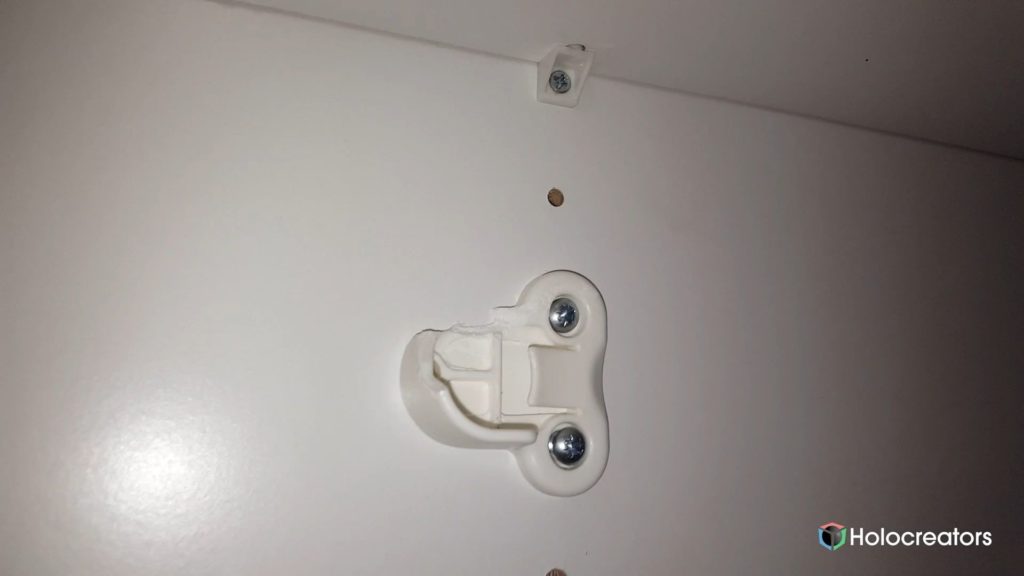
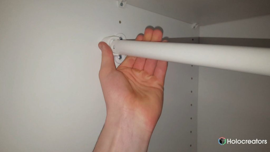
This broken clothes rail brace is part of an old IKEA closet. Unfortunately, it did not survive the last
move unscathed. The upper part of the brace was broken, so the rail did not hold anymore.
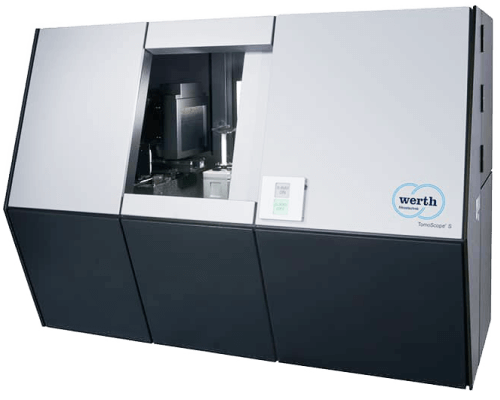
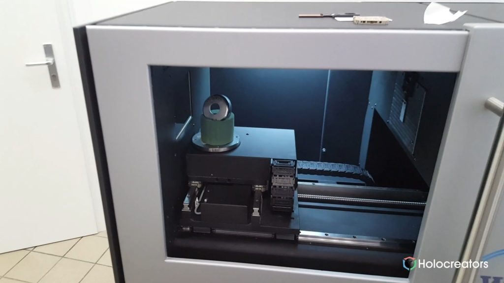
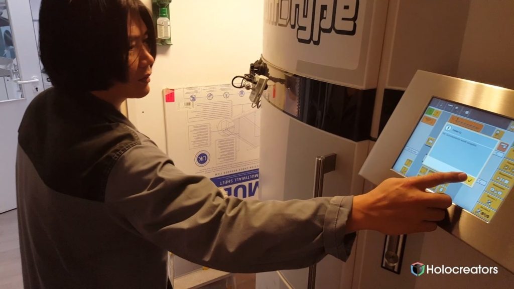
First, we 3D-scanned the part using 3D CT scanning. For this step, we visited the “Plastics Centre” in
Leipzig, where “Werth’s” brand-new industrial computed tomography 3D scanner is located. The
Tomoscope S works with X-rays. It looks a bit like an oversized microwave and has a lead door to
protect the operator.
A 3D CT scan works like this: The X-ray radiation is directed onto the part. The X-rays go through the
object and project an image onto a detector inside the CT Scanner. The part is placed on a turntable
that rotates slowly. This allows the object to be X-rayed from all sides. From these 360° sectional
images, a 3D model can be generated. In the end, the finished 3D scan can be exported in the STL
file format.
Reverse Engineering of the Part
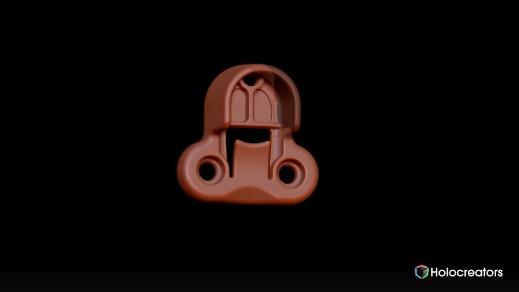
Secondly, we digitally reconstructed the object using software. During this process, we had the
opportunity to repair the faulty part. Thus, we were able to digitally restore the broken corners of
the clothes rail brace to their initial state. “Reverse Engineering” is the technical term for the
conversion from a 3D scan (STL format) into a CAD model (STEP format).
Deviation Analysis
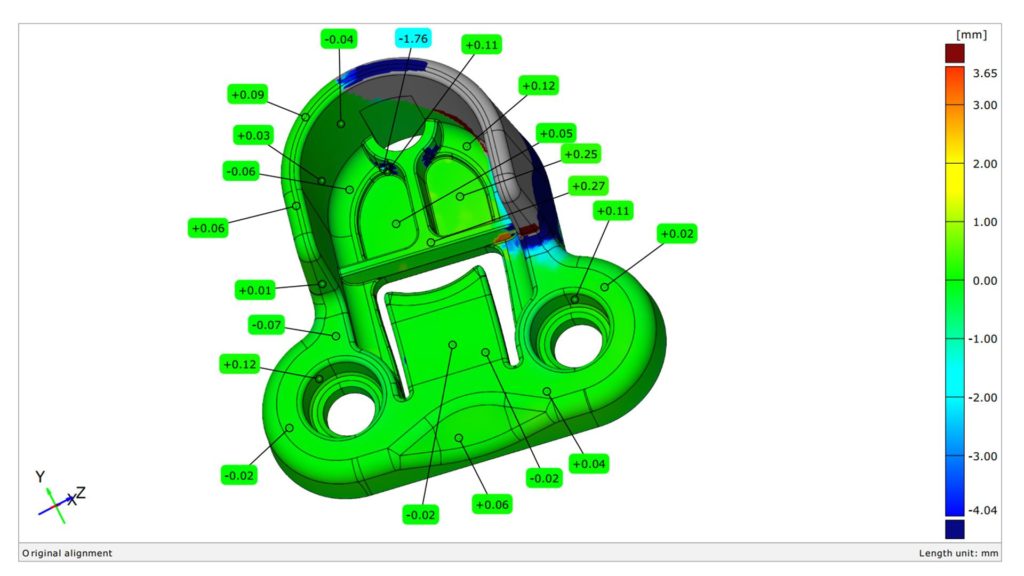
To investigate how far the reverse engineering of the clothes rail braces deviates from the original
3D scan, we created a deviation analysis. For this purpose, we use the free software “GOM Inspect”.
The green color indicates that the reconstruction is deviating very little from the original 3D scan.
deviation analysis here.
3D Printing of the Repaired Part
Next, our repaired clothes rail brace was 3D-printed. There are different 3D printing methods. We
have chosen the laser sintering process (SLS) because it produces very flexible and durable parts.
With the laser sintering process (SLS), on the other hand, the model is built up in a powder bed. The
laser first melts the contours of the object into a thin layer of powder. Then another layer of powder
is applied by a machine, and the laser fuses this layer precisely onto the previous one. This process is
repeated until the entire part is finished. In the finished piece, a fine stair-step pattern is visible;
these are the separation lines between the fused layers.
Removing the 3D-printed Part from the Powder Bed
After 3D printing, the part is inside a powder bed. The finished part must be dug out of this powder.
The surface of the part is sandblasted. Sandblasting smoothes the surface and removes any powder
remnants. In a final step, any remaining dust is blown off.
Project data for Download
We have provided the deviation analysis and the download link for the GOM Inspect software.
- Deviation analysis comparing 3D scan of IKEA part and reverse engineering (PDF)
- GOM Inspect (Software for a creating deviation analysis)
Conclusion
The reverse engineering and repair of the clothes rail brace worked wonderfully. The better the 3D
scan of a part, the easier the reverse engineering. In this case, we were able to work based on an
extremely accurate CT 3D scan. Surely this project could have been realized with simpler technology,
but it is an excellent example of what is possible.
Do you have a broken part that you want to repair with 3D scanning and 3D printing?
Holocreators offers professional 3D-scanning and reverse engineering services. We are happy to
create a 3D scan for you and support you with your reverse engineering projects. Please call us at +49 40 481133 or send an email info@holocreators.com
