Estimated reading time: mins

Reverse engineering and error propagation

Reverse Engineering and Error Propagation (3D Scanning and CAD) 03:56
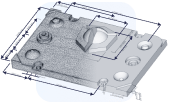
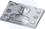
Reverse engineering enables us to create a copy of an object. For this purpose, the part is 3Dscanned, then the 3D scan data is converted into a CAD format, and finally, the part is manufactured. All these steps result in noticeable deviations. If an error adds up over multiple steps, then we call this error propagation.
Table of Contents
Error propagation between part A and B
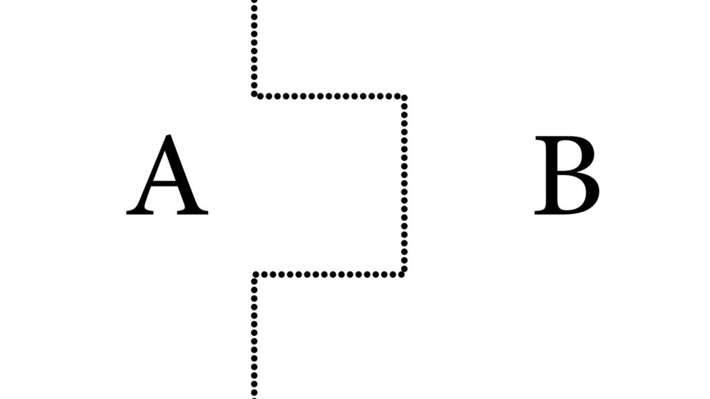
Swann Rack / Holocreators The original parts A and B fit together like a puzzle

Error Propagation During the 3D Scan

A 3D scan is made of two parts that fit together perfectly like a puzzle. Part A and part B. Our example 3D scanner has an accuracy of ±1 mm. This means that after the 3D scan of part A, the resulting 3D model could be 1 mm larger or smaller than the original. The 3D model of part B could also be 1 mm larger or smaller after the 3D scan. This means in a worst-case scenario, the whole puzzle is shifted by 2 mm and does not fit together properly.
Even more error propagation between part A and B
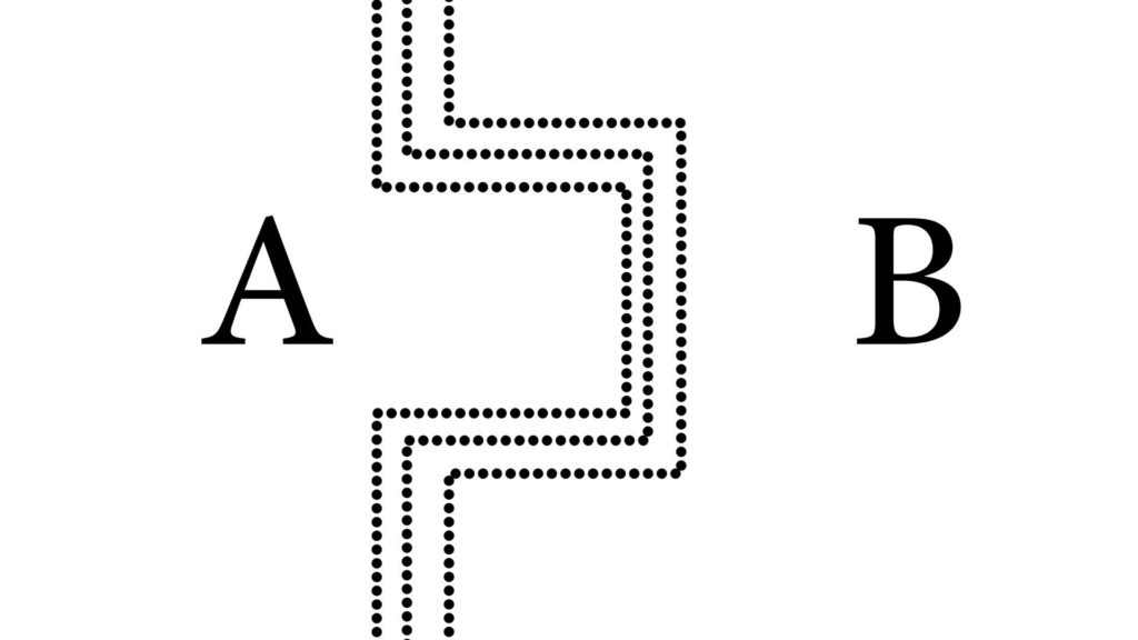
Swann Rack / Holocreators After the 3D Scan, there are deviations between part A and part B

Error Propagation in Reverse Engineering

After the 3D scan, we perform reverse engineering with parametric modeling and a history tree. This has an average deviation of up to ±0.25 mm from the original 3D scan. Adding the deviations of both processes, the puzzle may be off by 2.5 mm.
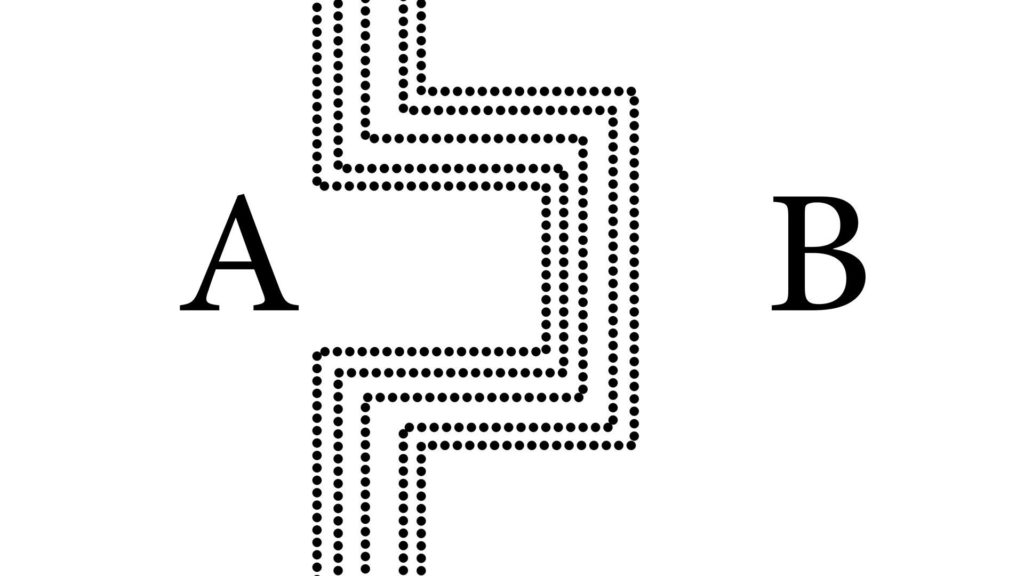
Even more error propagation between part A and B
Swann Rack / Holocreators After reverse engineering, there are even more deviations between A and B

Error Propagation in Manufacturing

During the last step, the 3D model is manufactured with metal 3D printing. Due to manufacturing deviations, the parts may be produced 0.2 mm larger or smaller. In a worst-case scenario, part A and part B now have a combined total deviation of 2.9 mm, and the puzzle pieces no longer fit together.
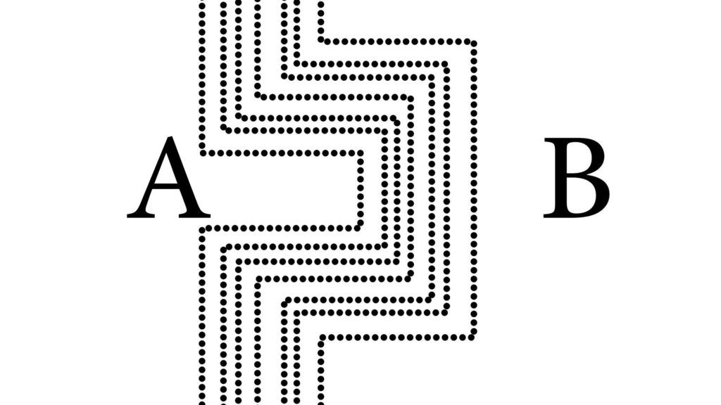
Maximum error propagation between part A and B
Swann Rack / Holocreators After production, part A and part B no longer fit together.

Conclusion

It is not possible to eliminate error propagation in reverse engineering, but it can be minimized. At each step of the reverse engineering process, it is important to choose the method that has the least deviation. Therefore, the most accurate 3D-scanning technique should be chosen. And for the reverse engineering process, it is up to the engineer to work as precisely as possible. There are also manufacturing processes that are more precise than others. For example, CNC milling is more accurate than 3D printing.

May we advise you on how to mitigate error propagation with your project?

Holocreators offers professional 3D-scanning and reverse engineering services. We would love to help you with your project and advise you, for example, on how to minimize deviations in your reverse engineering project. Please call us at +49 40 481133 or send an email info@holocreators.com
Swann has been enthusiastic about everything 3D for many years. His roots lie in analog holography, which brought him to digital 3D-modeling in 2011.

The rapid progress of various 3D-scanning techniques fascinated himso much thathe founded Holocreators together with his brother Miro Rack in 2015.

Ready to get started?
  • JPG, PDF, or PNG max 100 MB
    Drop files here or
    Accepted file types: jpg, png, pdf, jpeg, Max. file size: 100 MB.
    You may be interested
    Estimated reading time: mins
    With the help of specialized 3D scanners, you can 3D-scan people and animals. This allows you to create 3D models that can be 3D-printed or used for 3D animation. We'll show you three different devices that make such 3D scans possible.
    Estimated reading time: mins
    Kitbashing is associated with model making. It is composed of the words "Kit" and "Bashing". “Kit” refers to "model kit". So, when a model maker is "kitbashing", he blends parts from different model kits. Similar to a collage. The model maker combines several individual models into an entirely new model.
    Estimated reading time: mins
    A NURBS model consists of points connected by curves. A polygon mesh consists of thousands or millions of small triangles. CAD surface models are usually created using NURBS surfaces, while 3D scans are typically exported as a polygon mesh. The conversion from a polygon mesh to a NURBS model is called "reverse engineering".
    Estimated reading time: mins
    Swann Rack from Holocreators gave a presentation on reverse engineering at the Rapid.tech 3D Congress 2018. Reverse engineering allows an object to be reproduced using 3D scanning and subsequent conversion into a CAD format. In his presentation, Swann Rack talked about the different 3D scanning techniques and how the reverse engineering process works.

    Thanks you!

    Our representative will be in touch with you soon

    Thanks you!

    We are glad that you have subscribed to our newsletter
    sparks